DIY Sata to USB Cable Wiring Diagram: Illustration!
A DIY SATA to USB cable wiring diagram is a self-guided illustration that shows how to connect the wires of a Serial ATA (SATA) cable to a USB cable.
The diagram typically includes the color codes and labels of each wire, the connections to be made, and the sequence in which they should be connected.
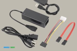
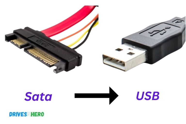
A SATA to USB Adapter is a piece of equipment that allows for a connection between a SATA device and a USB interface, such as a computer.
This makes it possible to use a hard drive or an SSD with a computer that does not have a SATA interface.
A DIY SATA to USB cable wiring diagram is useful when you want to create your own adapter, it helps in correctly wiring a SATA connector to a USB connector.
A DIY SATA to USB cable wiring diagram is a user-friendly guide for those who wish to make their own SATA to USB adapter.
This might be useful for those who have a spare hard drive or SSD they wish to use with a computer that lacks a SATA interface.
The diagram ensures that the correct connections are made, preventing any possible damage to the devices.
7 SATA Pin For DIY SATA To USB Cable Wiring Diagram
| SATA Pin | SATA Signal | USB Pin | USB Signal |
|---|---|---|---|
| 1 | GND | 4 | Ground |
| 2 | A+ | 3 | D- |
| 3 | A- | 2 | D+ |
| 4 | GND | 4 | Ground |
| 5 | B+ | 3 | D- |
| 6 | B- | 2 | D+ |
| 7 | GND | 4 | Ground |
Key Takeaway
Five Facts About DIY SATA to USB Cable Wiring Diagrams
Tools And Materials Needed
Create your own SATA to USB cable with this DIY wiring diagram.
All you need are the necessary tools and materials to get started. Easily follow this guide to save money and customize your own solution.
To successfully create a DIY SATA to USB cable, you will need a few tools and materials.
Here’s a list of what you’ll need:
- Soldering iron: A soldering iron is essential for soldering the wires and connectors together.
- Flux: Flux is used to remove any impurities and ensure a good bond between the solder and the wires.
- Solder wire: Solder wire is needed to join the wires and connectors.
- USB male connector: This connector will allow you to connect your DIY cable to a USB port.
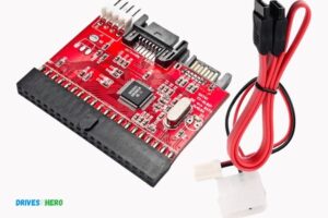
- SATA connector: The SATA connector is what you’ll use to connect the cable to the SATA interface of your hard drive.
- Heat shrink tubing: Heat shrink tubing is used to insulate and protect the soldered connections.
- Wire cutters: Wire cutters are necessary for cutting the wires to the required length.
- Wire strippers: Wire strippers help remove the insulation from the wires, exposing the conductors for soldering.
By having these tools and materials ready, you can ensure a smooth and successful DIY SATA to USB cable wiring project.
Remember to follow safety precautions when handling the soldering iron and always work in a well-ventilated area.
Pinout For Sata Connector
The pinout for the SATA connector is an essential aspect of understanding the DIY SATA to USB cable wiring diagram.
By following the correct pin configuration, you can easily convert a SATA connection into a USB connection for various purposes.
With this knowledge, you can create your own SATA to USB cable without any hassle.
The SATA connector plays a crucial role in connecting your storage devices to your computer. Understanding the pinout of the SATA connector is essential to ensure proper wiring and reliable data transfer.
We will dive into the explanation of each pin on the SATA connector, identify the power and data pins, and emphasize the importance of correct wiring.
Explanation Of Each Pin On The Sata Connector:
- Pin 1: Ground (GND): This pin establishes the electrical connection to ground and provides stability to the circuit.
- Pin 2: A+ (Transmit): This pin transmits data from the host to the device.
- Pin 3: A- (Receive): This pin receives data from the device.
- Pin 4: Ground (GND): Similar to Pin 1, this pin maintains the electrical connection to ground for added stability.
- Pin 5: B- (Receive): This pin receives data from the device.
- Pin 6: B+ (Transmit): This pin transmits data from the host to the device.
- Pin 7: Ground (GND): Another grounding pin for enhanced circuit stability.
- Pin 8: Reserved: This pin is reserved for future use and is currently not utilized.
- Pin 9: 3.3V (Power): The 3.3V pin provides power to the SATA device.
- Pin 10: 5V (Power): This pin supplies the SATA device with 5 volts of power.
- Pin 11: Reset (Optional): This pin is optional and can be used to reset the SATA device if required.
- Pin 12: Ground (GND): The final grounding pin for optimal circuit stability.
Identification Of Power And Data Pins:
- Power Pins: The 3.3V (Pin 9) and 5V (Pin 10) pins on the SATA connector provide the necessary power to the connected device. These pins are responsible for supplying stable power for the device to function properly.
- Data Pins: The transmit (Tx) and receive (Rx) pins, represented by A+ (Pin 2), A- (Pin 3), B- (Pin 5), and B+ (Pin 6), are responsible for the transfer of data between the host and the SATA device. These pins ensure smooth and efficient data transmission.
Importance Of Correct Wiring:
- Reliable Data Transfer: Proper wiring ensures that each pin on the SATA connector is correctly connected, enabling reliable and high-speed data transfer between the host and the SATA device.
- Avoiding Damage: Incorrect wiring may result in damage to the connected devices or even the motherboard. Following the correct pinout ensures that power and data signals are properly transmitted, reducing the risk of damage.
- Troubleshooting Made Easier: When the wiring is correct, troubleshooting becomes more manageable. If any issues arise, you can easily identify whether they are related to the wiring or other factors, helping you resolve the problem more efficiently.
Understanding the pinout of the SATA connector, identifying the power and data pins, and ensuring correct wiring are essential steps in successfully connecting and using SATA devices.
By following the correct pinout, you can maximize the performance of your storage devices and reduce the risk of data loss or hardware damage.
Soldering The Power Wires
Learn how to solder the power wires for your DIY SATA to USB cable using a detailed wiring diagram, ensuring a secure and reliable connection.
Step-By-Step Instructions For Soldering The Power Wires To The Sata Connector:
- Strip the insulation: Begin by carefully stripping about half an inch of insulation from the ends of the two power wires. This will expose the inner copper wires and allow for a clean connection.
- Preparing the SATA connector: Take the SATA connector and identify the two pins designated for power. These are usually labeled as “+5V” and “Ground.” Ensure that the connector is positioned correctly.
- Align the wires: Position the power wires in line with the designated pins on the SATA connector. The red wire should align with the “+5V” pin, while the black wire should align with the “Ground” pin. Double-check their alignment to avoid any mistakes.
- Apply flux: Apply a small amount of flux onto the pins of the SATA connector. Flux helps facilitate the soldering process by removing any oxidation and ensuring a strong bond between the wires and connector.
- Solder the connections: Heat up your soldering iron and allow it to reach the appropriate temperature. Once ready, gently touch the iron tip to the junction where the wire and pin meet. Apply solder to the heated area to create a secure connection. Repeat this process for both pins, ensuring that the solder adheres properly.
- Inspect for quality: After soldering, inspect the connections carefully to ensure that the wires are securely attached to the SATA connector. Avoid any excess solder or loose wires that could cause a short circuit or unreliable connection.
- Test for continuity: Use a multimeter set to continuity mode to verify that the soldered connections are conducting properly. Touch the multimeter probes to the solder joints and verify that the circuit is closed. This will confirm that the power wires are correctly connected to the SATA connector.
- Secure the connections: Once satisfied with the soldering and functionality, use heat shrink tubing or electrical tape to insulate and protect the soldered connections. This will help prevent any accidental short circuits or damage that may occur during use.
Remember to exercise caution and be attentive to details while soldering the power wires to the SATA connector. A properly soldered connection ensures a reliable and durable DIY SATA to USB cable.
In Summary:
Soldering the power wires to the SATA connector involves stripping the insulation, aligning the wires with the designated pins, applying flux, and soldering the connections.
Make sure to inspect the quality, test for continuity, and secure the connections with heat shrink tubing or electrical tape.
By following these step-by-step instructions, you’ll have a secure and reliable connection for your DIY SATA to USB cable.
Soldering The Data Wires
Learn how to solder the data wires for your DIY SATA to USB cable with the help of a comprehensive wiring diagram. This step-by-step guide ensures seamless connectivity for your projects.
Step-By-Step Instructions For Soldering The Data Wires To The Sata Connector
When it comes to DIY projects, one of the most common challenges is figuring out the intricacies of wiring. We will guide you through the process of soldering the data wires to the SATA connector.
Follow the step-by-step instructions below to ensure a successful connection:
Differentiating between data wires and ground wires:
- Data wires are responsible for transmitting and receiving data signals.
- Ground wires serve as a reference point for electrical currents.
Gather the necessary tools and materials:
- Soldering iron: Used to melt solder and connect wires.
- Solder wire: Contains a mixture of metals used to create a strong bond between wires.
- Heat shrink tubing: Protects the soldered connections from damages.
- Wire strippers: Used to remove the insulation from the wires.
- Helping hands: Provides stability during the soldering process.
Prepare the wires:
- Strip approximately 0.2 inches of insulation from the end of each data wire.
- Twist the exposed wire strands together to prevent fraying and ensure a smooth soldering process.
- Repeat this process for both the SATA connector and the USB connector.
Position the wires and connectors:
- Identify the corresponding pins on both the SATA connector and the USB connector.
- Align the data wires with their respective pins on the SATA connector.
- Ensure that the ground wires are not in contact with the data pins.
Solder the wires:
- Heat the soldering iron until it reaches the optimal temperature.
- Apply a small amount of solder to the tip of the iron to enhance heat transfer.
- Touch the soldering iron to the joint between the data wire and the pin.
- Allow the solder to melt and flow, creating a secure connection.
- Repeat this process for each data wire, ensuring a solid connection.
Insulate the connections:
- Slide a small piece of heat shrink tubing over each soldered joint.
- Use a heat gun to apply heat evenly to the tubing and shrink it around the connection.
- This step ensures insulation and protects against short circuits.
By following these step-by-step instructions, you will successfully solder the data wires to the SATA connector.
Take your time and double-check each connection to ensure a secure and reliable connection.
Connecting The Sata And Usb Connectors
Discover how to connect SATA and USB connectors with a DIY SATA to USB cable wiring diagram.
Easily follow step-by-step instructions for a seamless and efficient connection between these two essential components. Get started on your project today!
Guided Instructions For Connecting The Sata And Usb Connectors
When it comes to connecting the SATA and USB connectors for your DIY SATA to USB cable, it’s essential to follow the proper alignment and ensure a secure connection.
We will provide you with step-by-step instructions on how to connect the SATA and USB connectors successfully.
Here are the guided instructions for connecting the SATA and USB connectors:
- Preparation: Before getting started, gather the necessary tools and materials. You will need a soldering iron, solder wire, heat shrink tubing, electrical tape, wire cutters, and the SATA and USB connectors.
- Identifying the connectors: The SATA connector has seven pins, while the USB connector has four. Make sure to check the connectors and ensure you can differentiate between them easily.
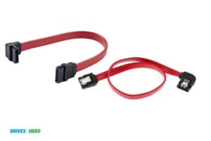
- Preparing the wires: Strip the outer insulation of the SATA and USB cables to expose the individual wires. Take note of the color coding of the wires on both cables as they indicate their functions.
- Matching the wires: Match each wire according to its function between the SATA and USB cables.
Here’s a quick reference:
- SATA 5V (red) to USB 5V (red)
- SATA GND (black) to USB GND (black)
- SATA D- (green) to USB D- (white)
- SATA D+ (white) to USB D+ (green)
Ensure that the wires are properly aligned before proceeding to the next step.
- Soldering the wires: Use the soldering iron to solder the matched wire pairs together. Apply a small amount of solder to each wire connection, ensuring a secure bond. Be careful not to apply excessive heat that could damage the wires or connectors.
- Insulating the connections: Once the wire connections are soldered, slide a piece of heat shrink tubing over each soldered connection. Heat the tubing with a heat gun or lighter to shrink it and provide insulation. Alternatively, you can use electrical tape to insulate the connections.
- Double-checking the connections: After insulating the connections, visually inspect each connection to ensure they are properly aligned and securely connected. Check for any exposed wires, and if necessary, reapply insulation.
- Secure the cables: Depending on your preference, you can use cable ties or electrical tape to secure the SATA and USB cables together, providing better organization and preventing accidental disconnections.
- Testing the connection: Once everything is securely connected and insulated, it’s time to test the DIY SATA to USB cable. Connect the USB end to your computer or other USB-enabled device and the SATA end to the storage device. If the connection is successful, your computer should recognize the storage device.
Congratulations! You have successfully connected the SATA and USB connectors for your DIY SATA to USB cable. Now you can enjoy the convenience of accessing SATA drives through USB interfaces.
Remember, proper alignment, secure connections, and careful insulation are crucial for a reliable and functional DIY SATA to USB cable. Enjoy your DIY project and the benefits it brings!
Checking For Continuity
The continuity of your DIY SATA to USB cable wiring diagram plays a crucial role in ensuring a smooth and efficient connection between devices. Checking for continuity is essential to avoid any disruptions or potential damage.
How To Use A Multimeter To Check For Continuity In The Cable
When it comes to DIY projects, understanding the wiring diagram of a SATA to USB cable is essential.
We will focus on checking for continuity in the cable using a multimeter. This step is crucial to identify any potential issues before proceeding further.
So let’s dive right in and learn how to do it:
Prepare your multimeter: Turn on your multimeter and set it to the continuity or resistance mode. Ensure that the probes are properly connected to the correct ports on the multimeter.
Identify the pins: If your SATA to USB cable has a connector, it’s important to identify the pins properly. Usually, SATA connectors have 7 pins, while USB connectors have 4 pins. Refer to the wiring diagram to identify the pins accordingly.
Check for continuity: Place one probe on the ground pin of the SATA connector and the other probe on the corresponding ground pin of the USB connector.
The multimeter should indicate continuity (a beep or close to zero resistance) if the connection is intact. Repeat this process for each pin and make sure they all show continuity.
Identify potential issues: If the multimeter doesn’t indicate continuity for any of the connections, there may be a problem with the wiring or the cable itself. You can use the continuity test to trace the issue by checking each wire connection individually.
Inspect for loose connections: In some cases, a loose connection might be the culprit behind a lack of continuity. Inspect each connection point carefully and ensure they are secure. If needed, solder or reattach any loose wires to establish proper continuity.
Test both ends of the cable: It’s important to check for continuity at both ends of the SATA to USB cable. Repeat the above steps for the corresponding pins on the opposite end of the cable to verify the continuity at both ends.
Check for shorts or cross-connections: While testing for continuity, also be on the lookout for any shorts or cross-connections between pins. This can occur if there is a wiring error or if the cable has been damaged. Use the multimeter’s continuity test to identify and resolve any such issues.
Document the results: As you perform the continuity checks, make sure to document the results. This documentation will come in handy if you encounter any problems later and need to troubleshoot or repair the cable.
By following these steps and using a multimeter to check for continuity in the SATA to USB cable, you will ensure that the wiring is correct and the cable is in proper working condition. This will save you from potential complications and help your DIY project proceed smoothly.
Troubleshooting Common Problems
Having trouble with your DIY SATA to USB cable wiring? Our guide provides a clear and concise diagram to help troubleshoot common problems. Quickly and easily resolve any issues and get your DIY project back on track.
Building your own SATA to USB cable can be a cost-effective solution for connecting a SATA hard drive to your computer’s USB port.
However, it’s not uncommon to encounter a few hiccups along the way. We will address common issues that may arise during the DIY process and provide troubleshooting steps and solutions to help you overcome them.
Common Issues Encountered When Building A Diy Sata To Usb Cable:
- Connection failure: Sometimes, your DIY SATA to USB cable may fail to establish a connection between the SATA hard drive and your computer. This can occur due to loose connections, incorrect wiring, or a faulty cable.
- Power supply problems: Insufficient power supply to the SATA hard drive can lead to connection issues or the inability to detect the drive. This may be caused by a weak or incompatible power source.
- Incompatible hardware: If the DIY cable is not compatible with your SATA hard drive or USB port, it can result in connection problems or even damage to your devices.
- Data transfer errors: Data transfer errors can occur when the DIY cable is not properly wired, leading to corrupted or incomplete file transfers.
- Drive not detected: In some cases, the computer may not detect the SATA hard drive when using a DIY cable, preventing you from accessing or using the drive.
Troubleshooting Steps And Solutions:
- Check connections: Ensure that all connections in your DIY SATA to USB cable are secure and properly attached. Reconnecting the cables can often resolve connection issues.
- Double-check wiring: Verify that you have correctly wired the SATA to USB cable according to the wiring diagram. Any incorrectly connected wires should be fixed to ensure proper functionality.
- Use a separate power source: If the power supply is insufficient, try using a separate power source, such as a powered USB hub or external power adapter. This can provide the necessary power to the SATA hard drive.
- Verify compatibility: Confirm that your DIY cable is compatible with your SATA hard drive and USB port specifications. Using incompatible hardware can lead to various issues.
- Test with different devices: If your DIY cable is not working with a specific computer or SATA hard drive, try connecting it to another device. This can help identify whether the issue is with the cable or the specific hardware.
- Update drivers: Ensure that you have the latest SATA and USB drivers installed on your computer. Outdated drivers can cause compatibility issues and affect the performance of your DIY cable.
- Test with a different cable: To eliminate the possibility of a faulty cable, try using a different SATA to USB cable for testing purposes. If the issue persists with a different cable, it may indicate a problem with your DIY setup.
- Seek professional help: If you have exhausted all troubleshooting steps and are still unable to resolve the issue, it may be best to seek assistance from a professional technician or consider purchasing a commercially available SATA to USB adapter.
By following these troubleshooting steps and solutions, you can overcome common problems encountered when building a DIY SATA to USB cable.
Remember to take precautions and consult professional help when necessary to ensure a successful DIY experience.
FAQ On Diy Sata To Usb Cable Wiring Diagram
What is a DIY SATA to USB cable wiring diagram?
A DIY SATA to USB cable wiring diagram is a schematic that illustrates how to wire up a SATA (Serial Advanced Technology Attachment) to a USB (Universal Serial Bus) cable, enabling the SATA device to be connected to a computer via the USB port.
What is required to make a DIY SATA to USB cable?
You will need a SATA data and power cable, a USB type A male connector, and some electrical wire. You may also need some basic tools such as wire cutters, wire strippers, and soldering tools, depending on your desired finishing method.
How do I connect the cable to my computer?
To connect your DIY SATA to USB cable to your computer, you will need to plug in the USB cable’s type A male connector into your computer’s USB port.
Then, using the wiring diagram, connect the data and power pins of the SATA cable to the appropriate wires of the USB cable.
What type of power supply does the cable need?
The power supply requirements of the DIY SATA to USB cable will depend on the device that is being connected to it. Therefore, you should consult the device’s user manual to determine the exact power supply capacity that is needed.
Can I use this cable to connect other devices to my computer?
Yes, you can use your DIY SATA to USB cable to connect other SATA devices, such as hard drives and optical drives.
Conclusion
To sum up, understanding the wiring diagram for a DIY SATA to USB cable can empower you to repurpose old hard drives with ease.
By following the step-by-step instructions and utilizing the right tools, you can convert your old storage devices into convenient external drives.
Remember to exercise caution and adhere to safety measures while working with electronics. This project not only allows you to save money, but also helps reduce electronic waste by giving new life to unused hard drives.
Whether you’re a tech enthusiast or just looking to expand your storage options, this DIY project is worth considering.
With a little bit of knowledge and effort, you can create your own SATA to USB cable and enjoy the benefits of portable storage. So, get ready to give your old hard drives a new purpose and unlock their potential!

Harold Williams is a senior writer and technical editor at Drives Hero with 20+ years of experience in IT administration. He specializes in storage systems, SSD reviews, and performance testing, bringing real-world insight to every guide.